|
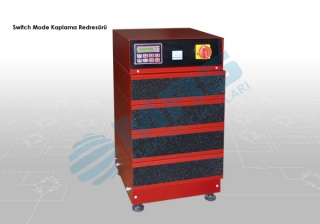
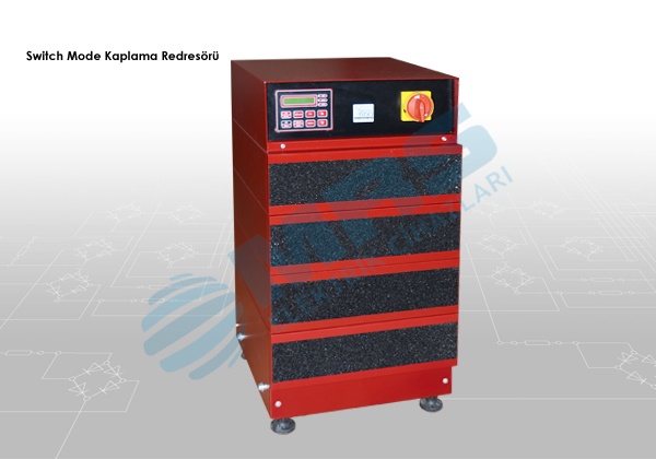
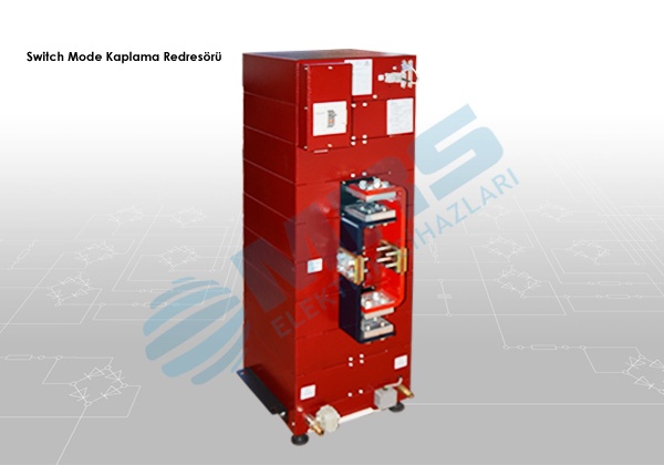
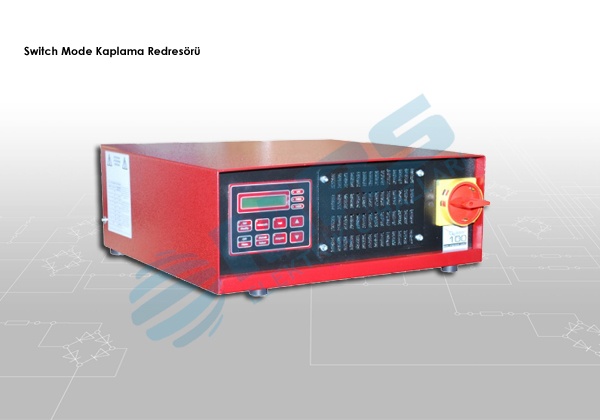
Switch Mode System
The system which saves 40% energy
Switch Mode rectifier tecnology symbolizes the latest point that the world reached ever on rectifier technologies. Being smaller, higher working yield,lower ripple ratio properties comparing to classic rectifiers ensures perfect solution on plating processes.
On Switch Mode rectifiers high frequency swtching technique is implemented to control transistor. Hence it doesn’t contain iron based transformator it is quite small and light. It is proved that it saves 20%-30% energy more because of its special technology comparing to thyristor controlled rectifiers at the same currentand voltage values. Considering situations like wrong rectifier choice, wrong application etc.. it can be observed that energy saving up to 40% is possible with these systems. High-speed IGBT technology
Modular power platform and multi-frame internal connection
Microprocessor Control System
Energy savings up to 40% compared to Thyristor Controlled Rectifiers
Compensation-free system, Power Height (cos Φ = 1)
Low output ripple 't (<% 2)
High precision voltage and current regulation
Quick response time and high stability load changes (~ 1ms)
Distributed power control
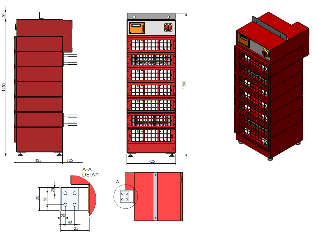
75% space saving compared with Thyristor Controlled systems, base size 43 x 43cm
60% lighter than the Thyristor Controlled systems
The main on-off switch on the front and the operator control panel
Easy access to all input / output connections on the rear
RS485 - RS232 serial communication unit
Automation Compatible System
PC / PLC Connection
Air-cooled system
|